32 |
Oilfield Technology
January
2016
over the last decade. As a result, increased well positioning from
surface has required many contractors and operators to ensure
that their anti-collision considerations are taken into account to
mitigate the potential for wellbore collisions and other dangerous
drilling events.
The historical approach of using MWD tools from surface has
seemed to be a prime choice: the same tool that will be used
at the kickoff point and the lateral will be in the hole from the
beginning. However, when looking at the output that is being
required (inclination and/or azimuth) versus the tool, personnel,
and lost-in-hole costs, in addition to the day rate, it quickly
becomes apparent that the potential cost efficiencies are a
fleeting reality.
Wireline tools are on the other side of the equation. These
tools, while simple to operate, can often take 30 to 45 minutes
for a round trip if using a single-shot wireline survey tool. This
time can be doubled if there are doubts concerning the accuracy
or validity of the survey, in which case the survey would need to
be taken again. Wireline surveys are often taken using a tool that
is dropped into the wellbore and retrieved, either via slickline or
in a ‘drop-and-trip’ fashion, where the tool is dropped into the
wellbore and retrieved once the entire drillstring is tripped out of
the wellbore. Adding to this time-intensive operation is the fact
that wireline tools are often used in an open wellbore, where the
stabilisers of the tool can become embedded in the formation,
thereby causing the recorded survey to be less accurate than
would be desirable.
Understanding that customers desire accurate downhole
surveys and a tool that is simple to operate has driven the
development of a new technology, FloSurvey
TM
real time survey
tool (Figure 1). This solution provides a bottomhole assembly
(BHA)-situated tool, in which surveys are sent to surface in
60 - 90 seconds from pumps on using a modified float valve as the
telemetry method. This telemetry method allows for surveys that
are rapid, accurate, and easily repeatable, saving both time and
rig cost.
The FloSurvey tool is based on
a modified float valve design as the
telemetry means. The main difference in
a conventional float valve versus the tool
is the use of a hydraulic brake system,
engineered ceramics, and electronic
components.
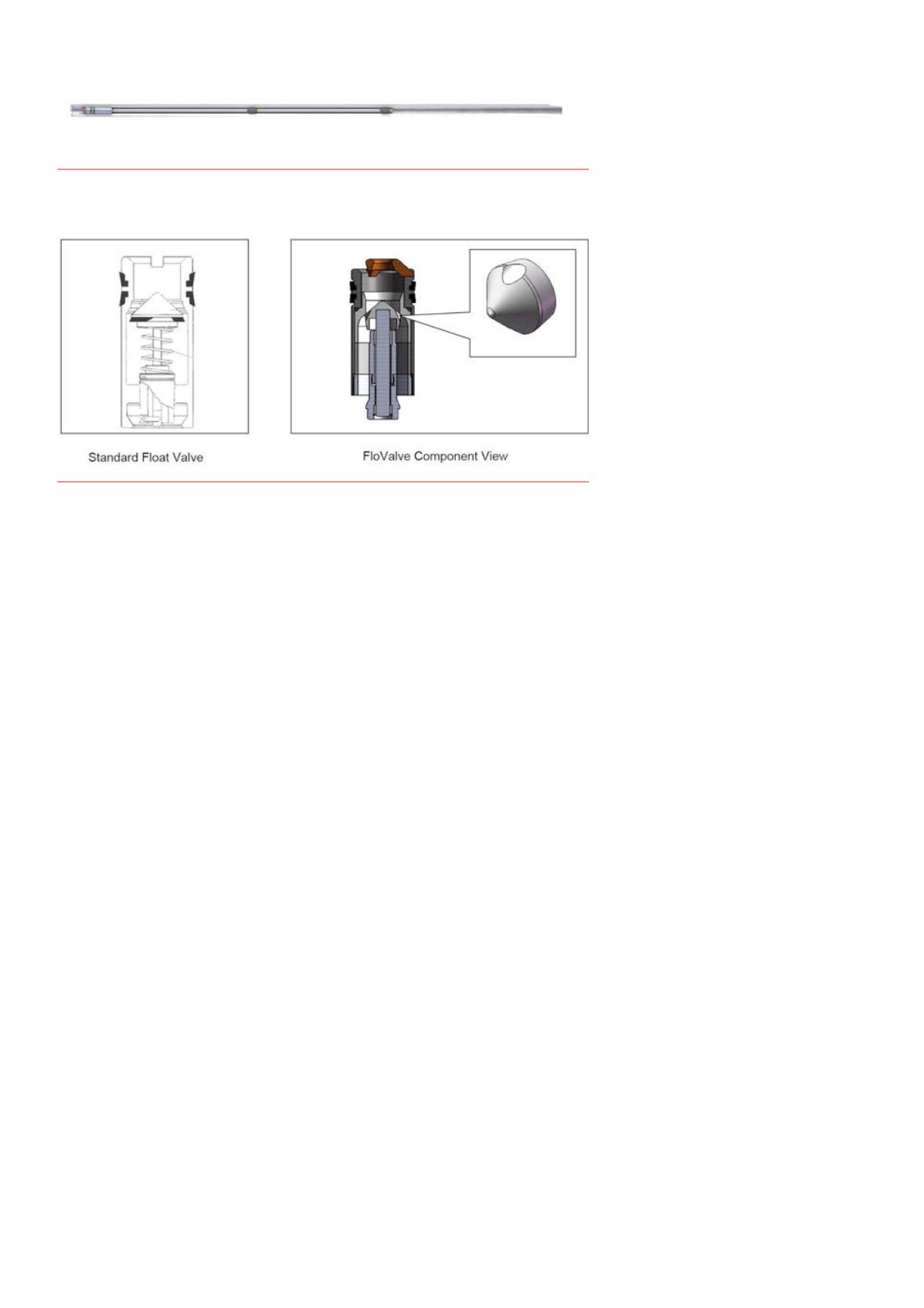
A comparison of the general differences
between this tool and a conventional float
valve is shown in Figure 2.
By incorporating modest improvements
to the general float valve design, this simple
tool has been transformed into a device
that can now be used to execute surveys
while connections are being made, reducing
the time it would normally require for a
traditional survey to be taken. The tool
runs inside 15 ft nonmagnetic drill collars
ranging from 4.75 in. outer diameter (OD) to
9.5 in. OD.
Theoryofoperation
The tool uses pressure reduction and
encoding telemetry software technology
to transmit the survey data to the surface.
This is achieved by controlling a modified float valve with an
accompanying hydraulic brake. Float valves are typically used
as check valves for well control purposes. This adaptation of a
float valve creates a loss in pressure that can be seen at the rig’s
standpipe using a conventional pressure transducer. The loss
in pressure is systematically reduced using the aforementioned
pressure reduction algorithms, creating a set of pulses analysed
at the surface using a specific surface decoder.
Utilising the onboard electronics package, the tool is capable
of sensing and transmitting downhole inclinations up to 20˚
in real time, and it is able to record inclinations up to 180˚ in
tool memory, with a resolution of 0.1˚. The tools are capable
of operating in environments up to 329˚F (165˚C) and have
an operating pressure range of 250 to 15 000 psi. The tool also
records each survey taken and stores it in the tool memory along
with temperature and other logged diagnostic data.
The transmitted survey signal is decoded with the aid of the
pressure transducer and displayed to the tool tablet located in
the driller’s cabin. The touchscreen tablet displays the survey
output in a user-friendly format and automatically detects,
decodes, and displays surveys on each connection or on demand.
The only required user input is for the driller to enter the bit
depth into the tablet software. Once the run is complete, the
technician can provide the client with a survey log, complete
with an ellipse of uncertainty and survey points for the entire run.
Figure 3 shows the components of the surface system.
Post-run, the customer can also elect to capitalise upon the
use of a comprehensive survey management service that takes
the memory data from the tool and applies multistation analysis
and magnetic corrections as needed, in order to provide both a
potential gyro-replacement offering, as well as increased survey
accuracy and wellbore placement information. An analysis
will also be conducted on the raw survey data from the tool’s
memory. In this service, the current International Geomagnetic
Reference Field Model, using spud date as the calculation
date, will be used for magnetic calculations. Tri-axial tool
Figure 1.
The FloSurvey tool installeda 15 ftnonmagnetic drill collar.
Figure 2.
Visual comparisonbetween standard float valve (left) and the FloSurvey tool float valve.


