January 2016
Oilfield Technology |
71
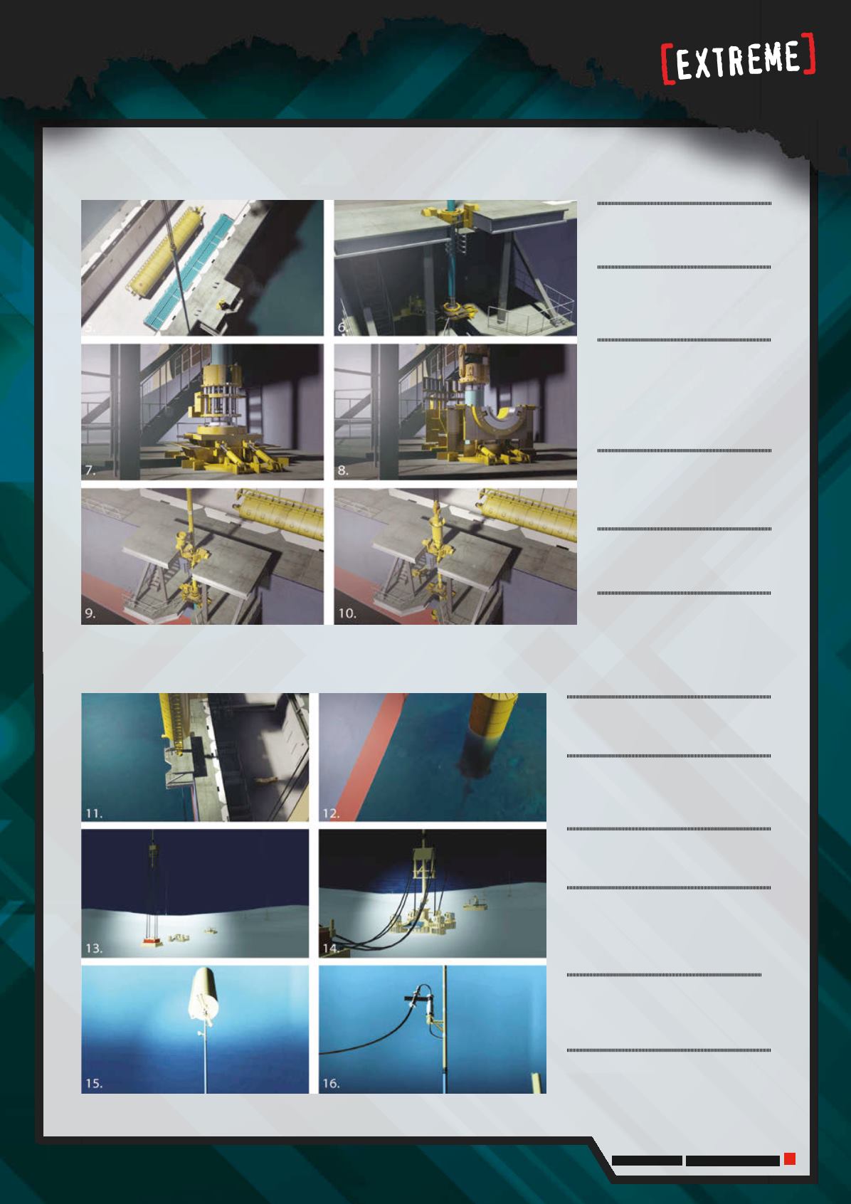
5.
Pipe section is upendedand
alignedwith the riser in the spider.
6.
Upper riser guide is used to align
the pipe segments to the hung off
risers.
7.
Connector assembly tool is
used to lock the pipe segment to
the hung-off riser. Spider table is
openedand riser is loweredand
hung-off.
8.
Additional pipe segments are
added to buildup the length of the
riser.
9.
Top riser assembly is upended
and connected to the hung-off riser.
10.
Riser is hung-off just below the
rotating latch receptacle.
11.
Buoyancy canwith rotating latch is
upendedand connected to the riser.
12.
Buoyancy can is floodedand
the crane is used to lower the riser to
operatingdepth.
13.
Clumpweight is placed on temporary
subsea foundation.
14.
Bottomrider assembly is pulled
down to engage to the rotating latch
to the receptable on the suction can
formation.
15.
Buoyancy can is ventedand crane
wire is released. Heavy lift vessel is
demobilised.
16.
Construction vessel installs flexible
jumper between riser andproduction
facility.


