June
2016
HYDROCARBON
ENGINEERING
56
Matrix PDM Engineering performed a limited analysis of the
response of a representative tank set
3
with the intent to
frame the effects. The methodology used an innovative
approach to rapidly assess seismic responses based on
peak ground accelerations. This article presents the results.
Background
Aboveground storage tanks in the US are designed using
API 650 Annex E and incorporated by reference in
regulatory codes. Seismic design consists of analysis of the
structural response to earthquakes and the measures taken
to contain that response. Earthquake effects are simulated
by applying artificial forces to a mathematical model of a
structure, resulting in responses similar to that caused by
an earthquake.
The maximum considered earthquake at a location in
the US is defined by USGS in the form of NSHMs. These
maps express spectral response parameters (S
s
, S
1
)
corresponding to ground motions due to a seismic event
with a specific probability of exceedance in any given year,
or, stated alternatively, with a recurrence interval (Figure 1).
The USGS maps, with the seismic responses or
parameters, are derived from a response spectrum
associated with the maximum considered earthquake
developed probabilistically. A response spectrum is a graph
that shows responses of a single degree of freedom system
over multiple frequencies for the design earthquake
(Figure 2). Building codes, regulatory agencies and
engineering standards set a specific design earthquake
based on a consensus assessment of risk and use the
parameters associated with that earthquake for structural
analysis and design. In ASCE 7 and API 650, USGS maps with
a recurrence interval of approximately 2500 years and
spectral response acceleration parameters S
s
and S
1
,
corresponding to periods of 0.2 sec. and 1 sec., respectively,
are used.
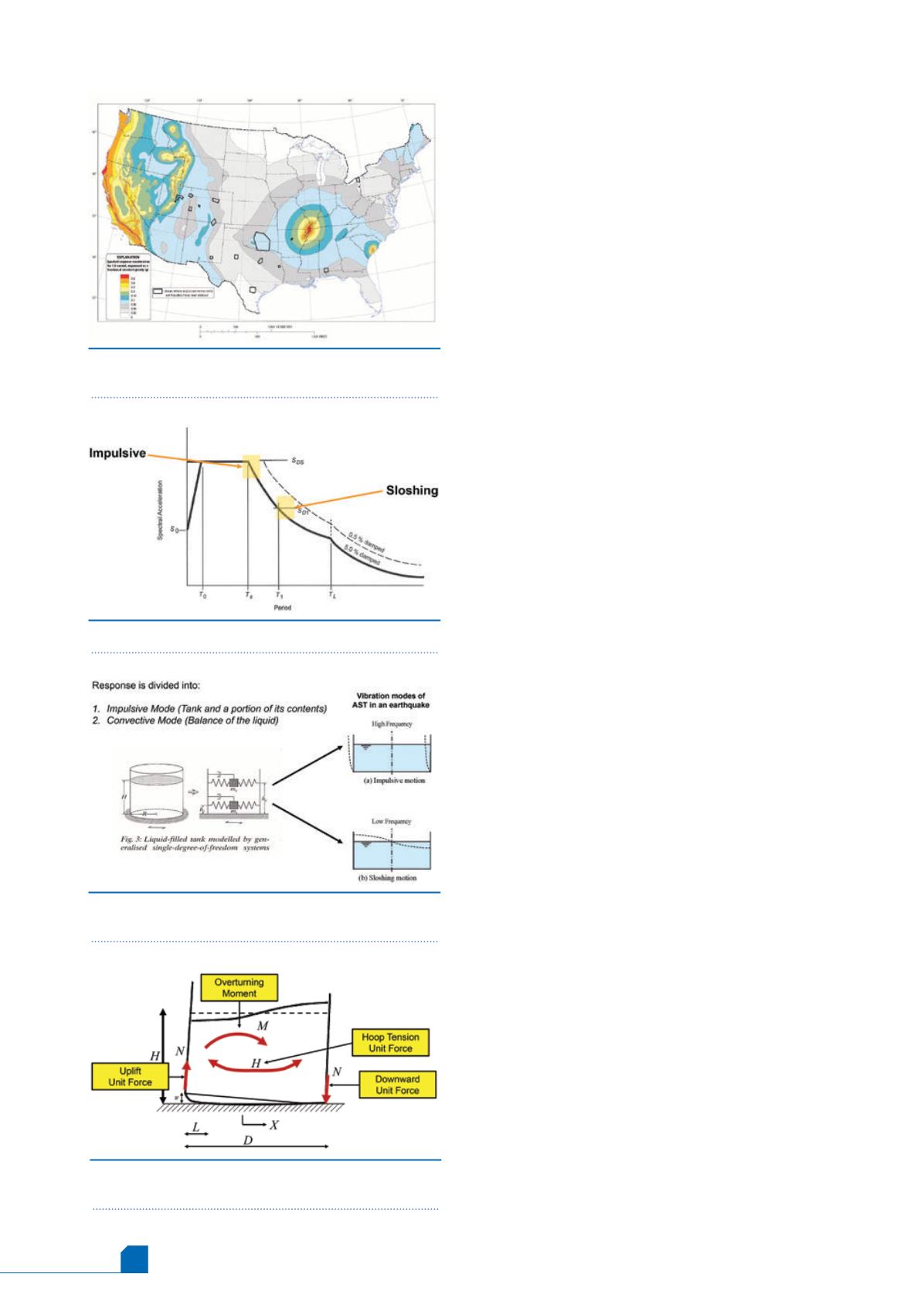
Responses of an aboveground storage tank to an
earthquake can be broadly divided into two modes: an
impulsive mode and a convective mode. The impulsive
response results from high frequency components (S
s
) of
the ground motion, which cause movement of the tank and
a portion of its contents inside. The convective response is
caused by the sloshing of the liquid and is affected by the
low frequency components (S
1
) (Figure 3). Pseudo forces, to
mimic the impulsive and convective responses, are
calculated using tank and fluid masses using seismic
parameters and are applied to a mathematical model of
the tank. The responses reviewed in tank seismic design are
lateral stability, dynamic hoop tensile stresses, overturning
moment, shell buckling and sloshing (Figures 4 and 5).
Typically, earthquakes are defined by magnitudes or by
intensities. Structural responses are related to energy
released and not to magnitudes. The energy release differs
significantly from one earthquake to another. While
magnitudes are meaningful in describing severity to the
general public, design engineers use seismic parameters
(S
s
, S
1
), not magnitudes, in the design process. Hence, there
is a need to determine these parameters for a rapid
evaluation of the effects due to occurrence of a seismic
event.
Figure 1.
2% probability of exceedance in 50 years
map of one second spectral response acceleration.
6
Figure 2.
Earthquake response spectrum notation.
1
Figure 3.
Liquid filled tank modelled by generalised
single degree of freedom systems.
7
Figure 4.
Seismic design process for ASTs; design
parameters for an unanchored tank.
8


