June
2016
HYDROCARBON
ENGINEERING
58
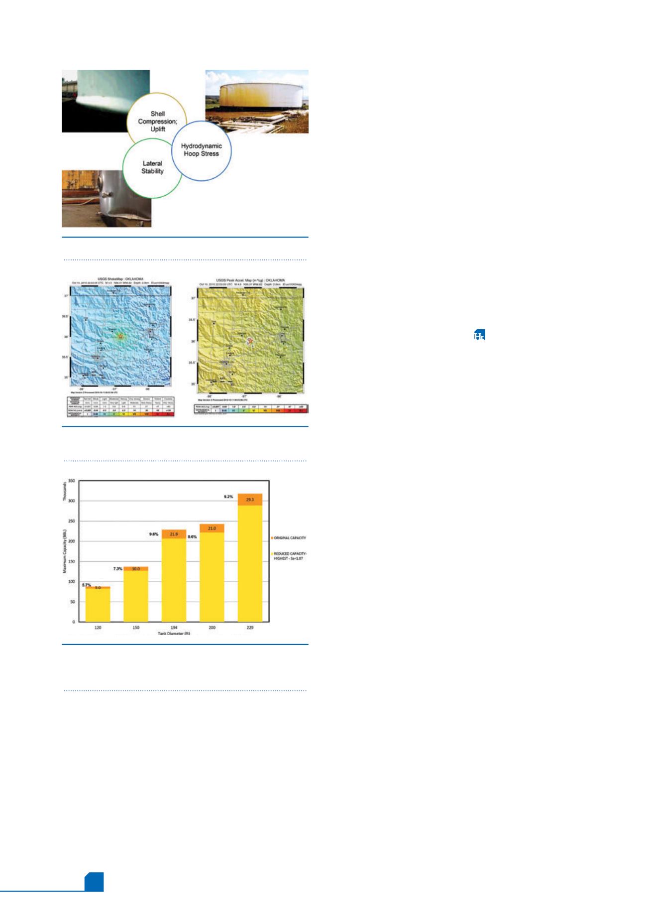
to identify the maximum liquid level that would stay within
the design limits of API 650 using the 60% g PGA. Trends
for guidance are shown in Figure 7. To properly evaluate a
specific tank, site specific and tank specific analysis is
required with the PGAs established with the input of
seismologists and based on a risk analysis.
While the evaluation performed by Matrix PDM
Engineering considered the tanks primarily, areas other
than the tank susceptible to secondary effects include:
piping attached to the tank, rolling ladders on the floating
roof, guide poles, floating roof seals, tank foam piping, etc.
Additional items in the terminals that are susceptible are
piping and piping supports inside buildings; differential
movement between piping, connecting structures and
platforms; and connections for stairways and walkways.
Methodologies for review of such infrastructure is well
documented in lifeline engineering processes.
5
Conclusion
In lieu of relying on recorded PGAs, there is a specific need
to design for a maximum considered earthquake, expected
PGAs and seismic parameters for a given site that would
cover the latest earthquake activity. Using this data, and as
part of earthquake preparedness, terminal operators may
proactively identify and, if possible, retrofit vulnerable
equipment including tanks, terminal components, pipelines
and support infrastructure. The plans should consider
including event specific terminal operating protocols and
post-seismic inspection and repair procedures for tanks,
terminals, pipelines and infrastructure. These reviews and
plans should be shared with local first response providers
and local regulatory authorities.
Notes
USGS published a 1% probability of exceedance in one year
seismic hazard forecast in March 2016,
13
after the
completion of this study. The data has not yet been
adopted either by building codes or regulatory agencies.
Acknowledgements
The following Matrix PDM Engineering professionals also
contributed to this article: Ken Erdmann PE, Golnaz
Bassiri PE and Chi Dang PE.
References
1. ‘Welded Tanks for Oil Storage, API 650,’ 12
th
Edition, March 2013 with
Errata December 2014.
2. ‘Minimum Design Loads for Buildings and Other Structures ASCE/SEI
7-05', November 2005.
3. The representative tank set consisted of six different open top
storage tanks designed to minimum requirements of API 650, in
Cushing with diameters ranging from 84 ft - 295 ft and with heights
of 48 ft and 56 ft. The results contained herein are specific to those
tanks and should not be utilised as a representation of results of any
other tanks.
4. MATHEU, E. E., et al., ‘Determination of Standard Response Spectra
and Effective Peak Ground Accelerations for Seismic Design and
Evaluation’, Army Corps of Engineers, ERDC/CHL CHETN-VI-41,
December 2005.
5.
FERRITTO, J. M., ‘Seismic Design Criteria For Lifelines’, Naval Facilities
Engineering Service Centre, Technical Report TR-2078-SHR, June 1997.
6. USGS site:
/
conterminous/2014/2014pga2pct.pdf.
7. YOSHIDA, ‘Review Of Earthquake Damages Of Aboveground Storage
Tanks In Japan And Taiwan,’ PVP 2014 - 28116, Proceedings of
the ASME 2014 Pressure Vessels & Piping Conference, PVP2014,
Anaheim, California, USA, July 2014.
8. VATHI, et al., ‘Seismic Response of Unanchored Liquid Storage
Tanks’, Proceedings of the ASME 2013 Pressure Vessels and Piping
Conference, PVP2013, PVP 2013 - 97700.
9. SEZAN, H., et al, ‘Structural Engineering Reconnaissance of the
17 August 1999 Kocaeli (Izmit), Turkey Earthquake’, PEER Report
2000/09, December 2000.
10. FISHER, E., et al., ‘Earthquake Damage to Cylindrical Tanks, Lessons
Learned’, Structure Magazine, March 2015.
11. USGS Site:
us10003mqq#general_region.
12. USGS sites.
13. PETERSON, M., et al., 2016 one year seismic hazard forecast for
the central and eastern US from induced and natural earthquakes;
USGS open file report 2016-1035, US Department of the Interior,
March 2016.
Figure 5.
AST design conditions.
7, 9, 10
Figure 6.
Shake map and peak acceleration map from
10 October 2015.
11
Figure 7.
If the highest PGAs recorded are used to
compute seismic parameters (48 ft tall) recommended
reduction in maximum capacity (liquid level).


