January
2016
Oilfield Technology
|
15
represent actual tool and pipe geometries. Details such as the actual teeth
on the inserts penetrating pipe are even included. While thismay bemore
expensive and time-consuming, it assures themost accurate results.
To verify the accuracy of the FEAmodels, FI regularly performs
slip-crush testing and correlates the test data to the data produced in
the analysis. This is accomplished by pull-testing various samples of
pipe (both casing and drillpipe), utilising various slips. FI performs the
testing using third-party testing andmonitoring firms, aswell as its own
2, 4, and 6million lb load frames (Figure 1). Since 2007, FI has performed
over 50 slip-crush tests on FI-manufactured slips, not tomentionmany
more tests on various types of other slips.
The company routinely performs two different types of slip-crush
tests: drift and strain gauge. When performing drift tests (Figure 2), FI
ascertainsmechanical properties and actual yield strength of a drillpipe
sample, which ismachined to exact desired specifications. Compiling
this data, an analytical model generates a theoretical slip-crush limit for
the drillpipe sample. A speciallymade drift is then lowered through the
drillpipe after applying an increasing array of loads. Slip-crush limit is
determined as the highest load at which the driftpasses successfully. In
thismanner, drift tests produce accurate indications of the global yielding
of drillpipe.
More recently, FI has begun delving even further into slip-crush
research and development by conducting strain gauge tests. This involves
strategically affixing strain gauges to the ID andODof a tubular and to
slips, followed by the slowapplication of a load until one of the strain
gauges registers a strain equivalent to⅔actual yield of pipe. This load
value is recorded. Then, the slips are rotated incrementally around the
tubular, and additional results are assessed. The data collected fromthis
test can be used to develop an overall picture of the stress patterns in the
pipe.
Though accurate, such laboratory tests cannot possibly duplicate
the dynamic factors at work in the field, where stresses on slips and
drillpipe tend to run higher due to vessel heave and slack-off weight on
the slips. With that inmind, the company also conducts strain gauge
tests on actual rigs landing high-load strings. A dynamic test (Figure 3)
partly entails typical laboratory strain gauge testing protocol, but the
tool is then shipped offshore with the strain gauges still in position.
The instrumented tool is utilised to land the string, setting the slips
every hundred or so feet. During the operation, strain data is collected
continuously.
As strains in the slip toes tend to run significantly higher during
dynamic testing than originally anticipated, it has been theorised that
the pipe encountersmore stress than expected due to the pretension
effect, which is caused by the transfer of the tubular fromthe elevator
to the spider. Fromthe elevator having set its slips on the drillpipe, the
pipe transferred to the spider has already incurredmillions of pounds of
pretension.
To confirmthis theory, pretension testswere performed. With
a drillpipe sample stabilised at both endswith spiders, FI utilises its
6million lb load frame to impartmillions of pounds of pretension to the
sample. The slips of a spider instrumentedwith strain gauges are then set
on the sample, and data is collected.
Based on the vast array of data derived fromdrift, strain gauge,
dynamic, and pretension testing, the company has developed a new line
of high-capacity drillpipe equipment (1000, 1250, and 1500 t), all equipped
with slips specifically designed for heavy landing strings. These particular
slips feature a higher slip-crush capacity than existing high-capacity rotary
slips presently on themarket.
Nonetheless, FI will continue to refine analytical models to be able to
better predict slip-crush capacity for various slip/pipe combinations.
Performance
On 2 June, 2015, FI and amajor operator successfully completed a job
in the Gulf of Mexico, using 1250 t casing tools to install the casing string
and the 1500 t landing string spider to land the string. In addition to this
installation requiring a run of 20 764 ftof 14 in. casing string in nearly
4000 ftof water, it entailed a final confirmed stringweight of 2 068 000 lb
(excluding 200 000 lb for top drive, bails, and elevator) – a newworld record
for stringweight.
On the same day, however, elsewhere in the Gulf of Mexico, FI and
anothermajor operator achieved evenmore, similarly utilising the 1500 t
Landing String Spider (Figure 4). Inwater depths exceeding 4000 ft,
22 154 ftof tapered (14 in. x 13.75 in. x 14.15 in.) casing stringwere landed,
and the final confirmed stringweight reached 2 215 000 lb (excluding
220 000 lb for top drive, bails, and elevator) – yet another newworld record
for stringweight, aswell as a record hook-load
(2 435 000 lb).
Figure 2.
Drift test.
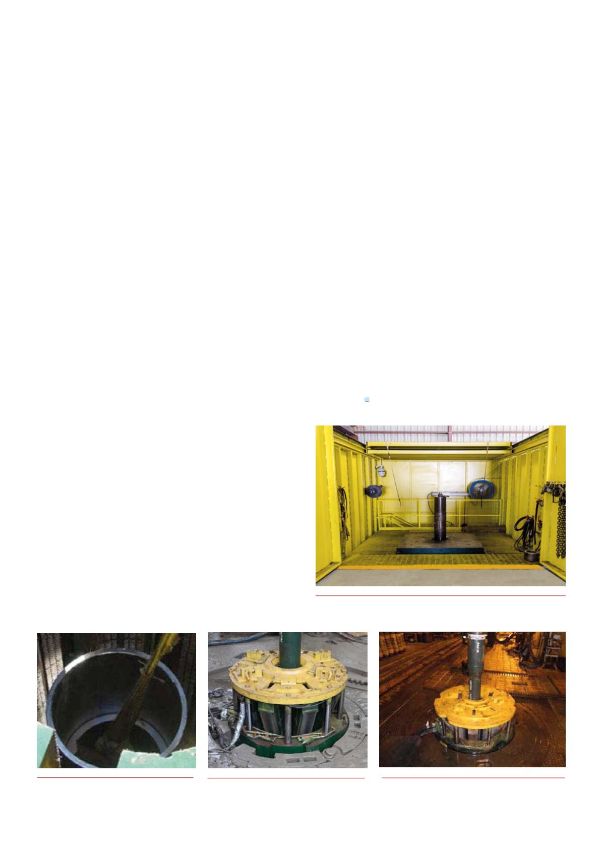
Figure 1.
6million lb load frame.
Figure 3.
Dynamic test.
Figure 4.
Frank’s 1500 t Landing String Spider.


