HYDROCARBON
ENGINEERING
28
tanks. This recovery will greatly reduce the
emissions from the combustion of the propane and
mixed refrigerant in the ground flare. Figure 2 shows
how the refrigerants will be recovered by using the
subcooled LNG and by being mixed in the LNG
transfer drum before being pumped into the LNG
storage tanks.
The LNG transfer drum includes a spray
connection to help capture the vapour refrigerants
and to maintain the pressure in the drum during the
recovery operation. A sparger located at the
bottom of the drum facilitates the vapour recovery
and reduces the time and volume required to
dissolve the vapours into liquid.
During liquefaction mode operation, the LNG
transfer drum operates at near atmospheric
pressure, but during the recovery mode the drum
will operate at around 35 psig to facilitate the
absorption of the refrigerants into the LNG. Table 1
shows the expected amounts of refrigerant to be
recovered.
Vacuum-jacketed piping
LNG produced at the LQF trains flows through the
commonly called ‘rundown’ line to be stored in the
LNG storage tanks. From there it is pumped via the
loading lines to the docks. All these lines are being
designed as vacuum-jacketed piping (VJP).
VJP consists of a pipe-in-pipe system with a
vacuum in between for thermal insulation purposes.
The insulation performance of VJP is 10 times better
than conventionally insulated piping, which means
that the LNG remains cold for longer periods of
time, generating 10 times less boil-off gas (BOG),
which in turn creates energy savings. In addition, no
recirculation of LNG is required to keep the piping
cold between LNG ship loadings. Typical VJP
systems for LNG have an outer jacket made of
carbon steel, which is not rated to withstand the
temperatures and pressures from the LNG.
Freeport LNG upgraded all of its new VJPs with an
outer jacket of 304 stainless steel (the same as the
inner piping), which will prevent the LNG from being
released into the atmosphere upon a failure of the
inner piping. Piping bowing and the effects from
LNG jetting impingement in the outer piping were
taken into account during the design to ensure that
the outer jacket will not fail due to a malfunction in
the inner piping.
Table 2 shows the estimated piping lengths and
annual energy savings from implementing VJP
systems in the Freeport LNG liquefaction project.
Electric motors for main refrigerant
compressors
Three General Electric 75 MW variable speed
electric motors drive the low pressure mixed
refrigerant compressor, medium pressure and high
pressure mixed refrigerant compressors combined,
and the propane compressor.
Figure 3.
Boil-off gas recovery flow diagram.
Figure 4.
Main cryogenic heat exchangers from APCI are the
tallest features of the LQF facilities.
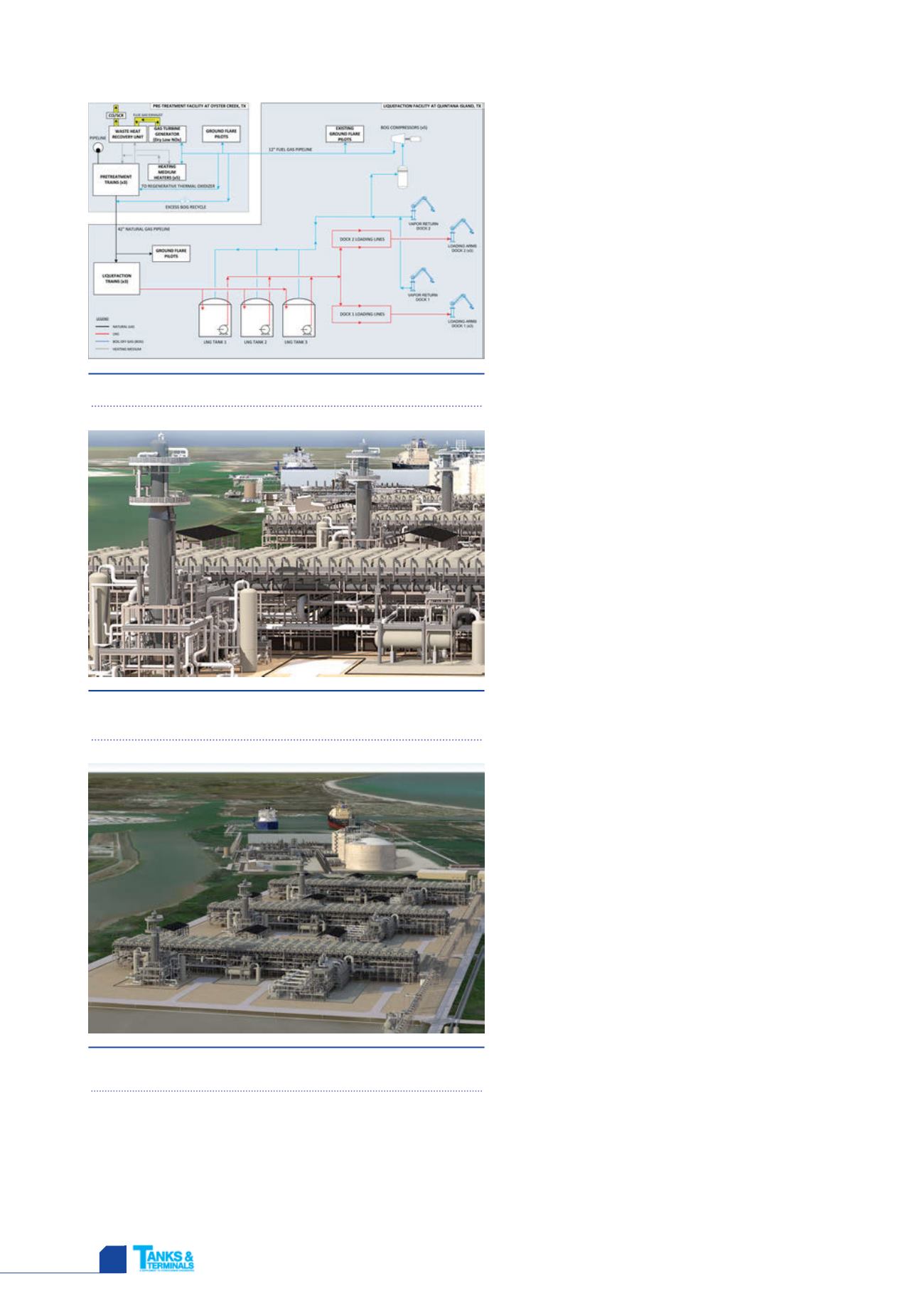
Figure 5.
Overall 3D model rendering of Freeport LNG's LQF
facilities.
nitrogen, methane, ethylene and propane) and propane into the
LNG by using an LNG transfer drum, in which these fluids will
be absorbed by subcooled LNG. Freeport LNG liquefaction
trains feature a unique network of drains and vents that will
allow the collection of the propane and mixed refrigerant to be
injected into the LNG that will be stored in the LNG storage


