June 2016
Oilfield Technology
|
23
test runs occasionally showed promising ROP potential, they
typically became damaged beyond repair in intervals as short
as 500 ft. Such a lack of durability can be attributed to the
inability of gouging inserts alone to withstand harder and more
consolidated formations.
The Generation 1 design (Figure 2) features densely spaced
gouging inserts positioned well above the PDC cutting structure
– this results in very smooth drilling behaviour and excellent
durability. Even the first prototype bit produced positive
field results on its initial runs, thereby proving the inherent
performance advantages of the hybrid technology. However,
due to the excellent condition of the majority of the dulls, the
development team concluded that more ROP could be gained by
making a few key design changes.
Secondgeneration
The Generation 2 design (Figure 2) features more widely
spaced gouging inserts positioned closer to the PDC cutting
structure. This enables the PDC cutters to engage more actively
in the formation, to significantly boost ROP while retaining
the durability and control benefits of the hybrid technology.
Wider insert spacing also allows for
increased face volume and flexibility
in hydraulic layouts, enabling the
bits to clean and cool both cutting
structures effectively at higher ROP.
One of the most consistently
successful applications for
Generation 2 designs is in
Western Canada, drilling 2000 ft
surface intervals in a single run that
would otherwise require at least
one rollercone and one PDC bit.
Operators in these applications save
many hours by eliminating a trip
while even occasionally matching
the ROP of a PDC bit. The excellent
steerability of these designs has also
been demonstrated by numerous
other runs on directional assemblies
in bit sizes ranging from 6 ¼ in. to
24 in., many of which replaced rollercone bits and successfully met
demanding directional requirements.
2
Thirdgeneration
The company identified even more opportunity for Pexus
technology by directly targeting the conventional PDC market.
Generation 3 designs (Figure 2) were developed to match or
exceed the ROP capability of PDC bits in these applications,
while using the Pexus cutting structure to improve torque
response and protect the PDC cutters from damage. They
generally contain fewer blades than conventional PDC bits – for
example, in one 12 ¼ in. diameter Western Canadian application
that typically uses 616 (six blades, 16 mm cutters) or 519 type
PDC bits, more aggressive 419 type Pexus designs have achieved
continued success in terms of both ROP and durability.
3
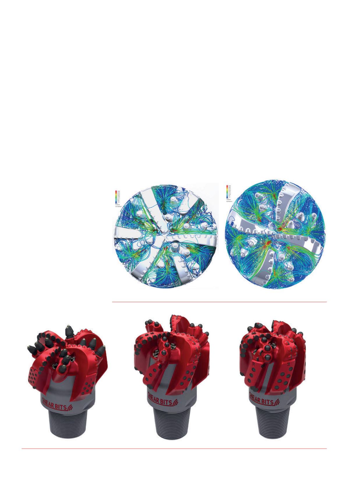
Generation 3 designs also feature a significant change in
hydraulic layout that aims to improve cooling in thermally
demanding environments, and provide superior cleaning in
high ROP applications. Computational fluid dynamics (CFD)
analyses were performed to illustrate the positive effects of
having dedicated flow paths directly in front of each cutting
Figure 3.
CFD comparisonbetweenGeneration 2 (le ) and 3 (right) Pexus hybriddesigns.
Figure 4.
From le to right: a 12¼ in. hybridbit, a 8¾ in. hybridbit, anda 6¼ in. hybriddirectional bit.


