constructed to the DNV OS-F101, which is currently used for 65%
of new subsea pipelines around the world. For onshore pipelines
or subsea pipelines designed to other codes – especially vintage
pipelines – welded sleeve repairs may not be possible, as a too
high HAZ hardness may be obtained. In such cases, alternative
repair methods using a combination of bolted full encirclement
split sleeves injected with epoxy grouting may be an alternative.
Welding considerations
While there are concerns when welding onto an in-service
pipeline, it can be relatively straightforward provided that well-
established guidance is followed. The first of these concerns
is for ‘burn-through’ – or blowout as it is sometimes referred
– where the welding arc causes the wall of thin-wall pipe to be
penetrated. The second concern is for hydrogen cracking, since
welds made in-service tend to cool at an accelerated rate as the
result of the flowing contents ability to remove heat from the
pipe wall.
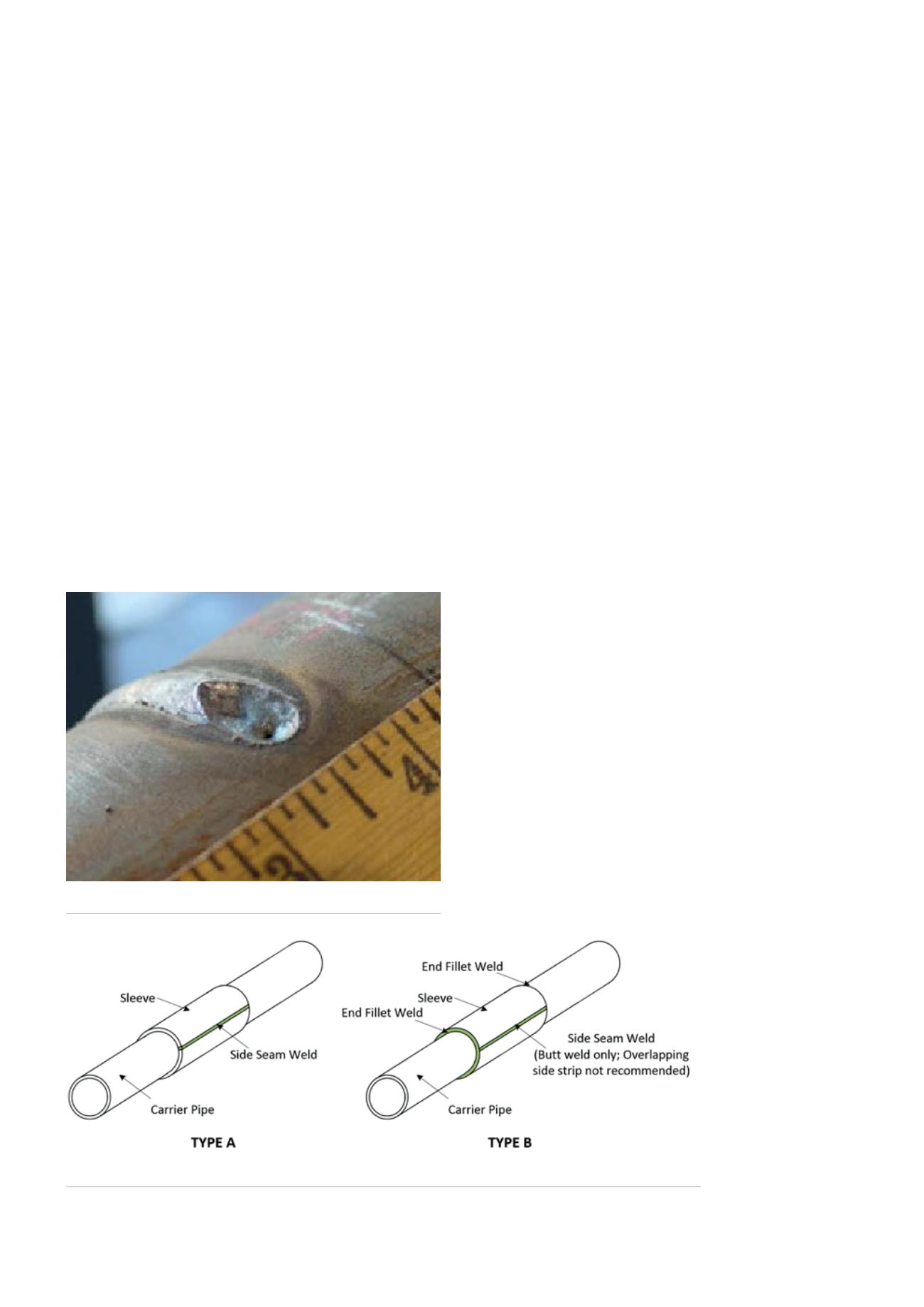
A burn-through will occur when welding onto a pressurised
pipe if the unmelted area beneath the weld pool has insufficient
strength to contain the internal pressure. A burn-through
typically results in a small pinhole in the bottom of what was
the weld pool (Figure 2). The risk of burn-through will increase
as the pipe wall thickness decreases and the weld penetration
increases.
The most useful tool for evaluating and preventing the risk
of burn-through is thermal modelling analysis using either the
Battelle model or the PRCI model. These computer models
predict inside surface temperatures, which must be kept below
982˚C (1800˚F), in order to minimise the risk, as a function of
the welding parameters (current, voltage, and travel speed),
geometric parameters (wall thickness, etc.) and the pipeline
operating conditions (contents, pressure, flowrate, etc.). The risk
of burn-through for a given application can then be evaluated
based on these parameters, which in turn help to determine
the limiting welding parameters for a given set of operating
conditions.
To prevent hydrogen cracking in welds made onto in-service
pipelines, the weld hydrogen level should be minimised by using
low-hydrogen electrodes or a low-hydrogen welding process.
As added assurance, welding procedures that minimise the
formation of crack-susceptible microstructures should be used.
The importance of controlling hydrogen levels for welds
made onto in-service pipelines is well established. The results of
recent work show that close control of hydrogen level allows
HAZ hardness in excess of 350 HV to be tolerated. Storage and
handling of low-hydrogen electrodes is an inexact science at
best, even though general guidelines for their use are available.
The hydrogen level of welds made using low-hydrogen
electrodes can vary widely depending on a range of factors.
Many of the potential problems associated with minimising
hydrogen levels for welds made onto in-service pipelines,
and therefore minimising the risk of hydrogen cracking,
can be addressed by using low-hydrogen electrodes with
supplementary designators that limit weld hydrogen levels. A
standard set of procedures can be qualified that cover a range of
conditions. Simple guidelines can then be developed so that the
simplest procedure can be selected for a specific application.
Available technologies and techniques
Welded sleeves
Early works by Battelle in the 1970s show that welded full
encirclement split sleeves can provide structural strengthening
and are capable of completely restoring the strength of the
damaged area. Type A sleeves are not welded to the pipe at
each end. However, sleeves need to be welded to contain
leaking defects and provide resistance to axial stress. So-called
Type B sleeves are usually welded using a special fillet welding
procedure, involving
weld buttering layers
before the fillet weld is
completed (Figure 3).
For leaking
pipelines and pipelines
with deep girth weld
flaws, DNV GL has
been involved in
developing welding
procedures for repairs
of live pipelines not
requiring shutdown.
Some of the repairs
have involved
Figure 2.
Typical burn-through on 0.125 in. (3.2 mm) thick pipe.
Figure 3.
Type A and Type B tight fitting full encirclement split sleeves.
38
World Pipelines
/
MARCH 2016


