50 |
Oilfield Technology
January
2016
within the Llanos basin of the Casanare territory. Canacol wanted
to improve the overall cement integrity of wells being drilled, which
were directional with an average of 22˚ deviation in their 8 ½ in.
and 7 in. sections. The new dynamic cementation technique was
applied to more than 15 wells with highly satisfactory results.
Casestudy two
Dynamic cementation was employed in the Eastern Hemisphere for
the first time in 2014. Due to concerns over oil price instability and
high drilling costs, the operator was challenged to find new ways to
reduce costs. The company highlighted rig NPT associated with slow
transition time between traditional casing running and cementing.
This is a recurring source of NPT in the Eastern Hemisphere as
transition times can take anywhere between two to three hours
on land and three to five hours offshore. Dynamic cementation
techniques were able to greatly reduce the NPT by allowing for a
much quicker transition from casing running to cementing.
Another costly process uncovered in the assessment was the
remedial work that was required after a poor quality cement job,
typical of traditional casing and cementing practices. Computational
fluid dynamics (CFD) simulation and 3D cement bond log-variable
density log (CBL-VDL) charts indicated a mud displacement efficiency
of approximately 50 - 60% on these wells. The ultrasonic images
(USI) revealed mud channelling, irregular CBL amplitude and weak
formation signal. All possible indicators of issues that could affect the
overall zonal isolation and the integrity of the set-cement sheath.
Dynamic cementation practices were introduced to address the
poor cementing issues that are seen in the industry today. A CDS
tool and cement swivel were utilised to rotate the casing strings at
20 rpm and reciprocate at 4 ft/min during cementing operations.
Analysis of the resulting USI and 3D CBL-VDL charts showed optimal
isolation, high-quality, well-bonded cement and virtually no trace
of unwanted fluids. In addition, the CBL amplitude was low and flat
while VDL indicated strong formation signal.
Collecting field results from cases such as these have
contributed to the growing body of knowledge on cementing issues
and potential solutions. Dynamic cementation allows the operator
to reduce unnecessary NPT during operational transitions and to
avoid the need for costly remedial cementing. This increases rig
efficiencies and produces higher quality cementation, ensuring the
long term economic viability of the well.
References
1.
Holt, C., Lahoti, N., ‘Dynamic Cementation Improves Wellbore Construction
and Reduces the Hazards of Groundwater Contamination in Shale Plays’ SPE-
Canadian unconventional Resources Conference, Calgary Alberta, (2012).
Figure 5.
Displacement efficiency is the degree or ability of one fluid to
displace another. This canbe calculatedas: displacement efficiency =
current area/ total annular area = cementedarea + displacedarea.
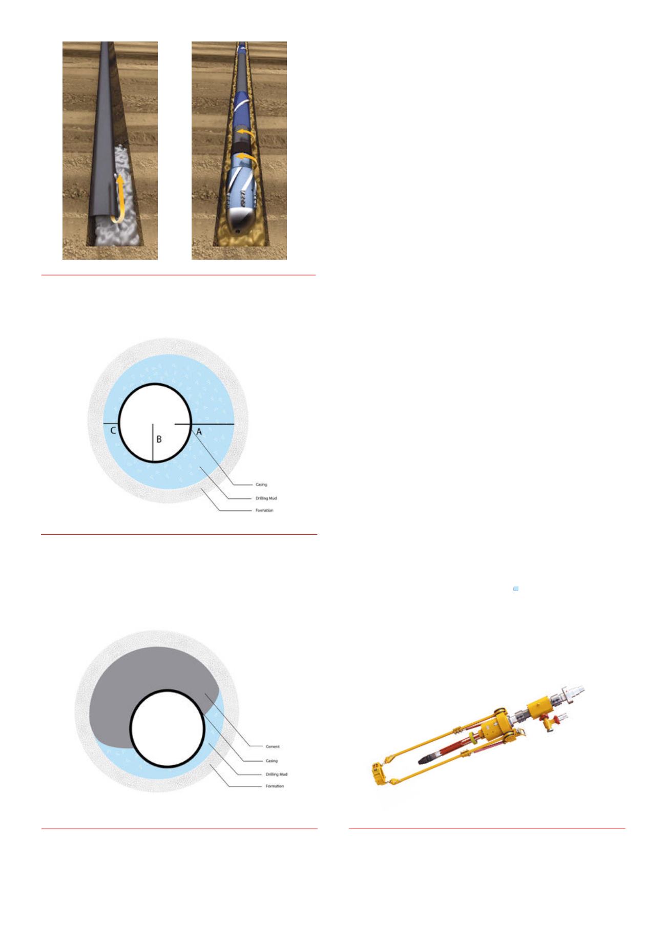
Figure 4.
Poor stand-off leads to poormuddisplacement efficiency
andpoor zonal isolation. Stand-off = C/A-B, when A =wellbore diameter,
B= pipe diameter, C = shortest distance between the pipe and the
wellborewall. Inaperfect scenario, when the casing is at the centre,
A-B= Cand standoff = 1 (100%).
Figure 3.
Pipemovement during cement placement aids inmore evenly
displacingmud, which can otherwise become trapped on the narrow
side of the eccentric annulus.
Figure 6.
Tesco cement solution : the CasingDrive System
™
, cement
swivel, ball launcher and TesTork.


