54
|
Oilfield Technology
January
2016
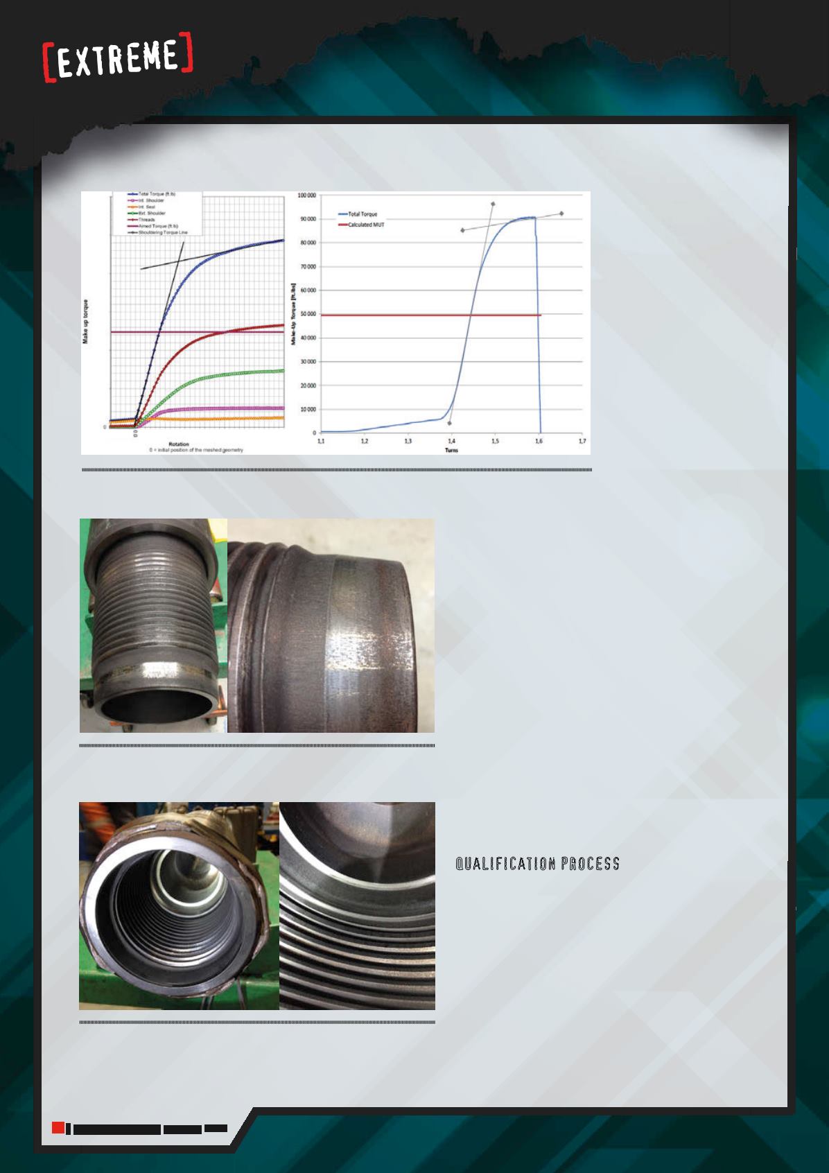
Figure 3.
Make-up curve comparisonbetween finite element analysis (FEA) (left) andphysical test (right) –
Newgeneration gas tight connection 57: 7⅛ in. x 4
⅜
in. – Grade 130 ksi.
included mechanical
performance, robustness
and ease of use.
Some of the
main characteristics
incorporated into the
connection design
included:
The ability to
function as a drilling
and completions
connection.
The ability to handle
high torque, up to
100% more than
comparable sized API
connections provided
by the primary and
secondary shoulders
and the thread design.
The connector taper and thread design allows for
deeper stabbing and quicker make-up.
Elliptical thread root design provides better fatigue
resistance.
Reversed angle on thread crests reduces risk of
wedging.
The slim design of the connection improves hydraulic
performances, clearance, and fishability.
The preferred location to place a metal seal in a double
shoulder drill pipe base connection is the cylindrical part
of the pin nose. This section is sufficiently thick to provide
stable performance through all the loading cycles of the
connection, guaranteeing a gas tight seal.
The final design of the connection seal included a
soft taper on the pin nose outside diameter and a seat
with a large radius on the box. The taper provides the
connector with a smooth contact increase during the
make-up phase (Figure 1) and the seal radius helps
distribute the stress on a large area, thus reducing the
risk of galling (Figures 1 and 2).
Qualification process
Review of standard drilling practices and critical
concerns during the risk assessment of drilling and
hydraulic fracturing, resulted in the definition of a series
of qualification tests to be performed.
After developing the concepts, which were based on
analytical calculations, the most promising concept was
optimised using finite element analysis (FEA), before
performing any physical tests.
This intensive qualification programme was intended
to confirm expected performances and validate field
applicability for the new connection.
Figure 5.
Next generation gas tight connectionBOX side after 100
make-and-break.
Figure 4.
Next generation gas tight connectionPIN side after 100
make-and-break.


