valves to stick in open (Figure 3). Known as steam contamination,
this can also cause an unsafe condition.
In lube oil systems, where critical instrumentation shares the
same oil system as the steam turbine, contamination such as
particle or condensate can be introduced to the valve’s actuator
(Figure 4). This can cause the valve’s actuator to stick open and
not activate when an emergency trip is required, thus causing an
unsafe condition.
Theory of operation
Traditionally, trip, trip-throttle and/or swing disc non-return valves
are reset and allowed to be actuated once positive minimum
oil pressure is established at the valve. The loss of oil pressure –
which is initiated by either a solenoid or mechanical trip valve
– will cause the trip or trip-throttle valve to immediately close in
less than 0.5 or 0.3 secs, depending on the valve type.
Steam turbine trip systems
Steam turbine trip systems come in a variety of options. Over the
years, Steam turbine OEMs have designed their own trip systems
that can typically be classified as mechanical or electrical trip
systems. Both are based on speed and work within a specified
range.
Mechanical trip systems can be a simple spring-loaded plunger
that triggers a trip or flyweights that trigger the mechanical trip.
The trip can be caused via linkage or the loss of oil pressure to
the trip-throttle valves, which causes those valves to immediately
shut off steam to the steam turbine.
Electronic trip systems incorporate an electronic over-speed
device that monitors the speed of the steam turbine. Once the
electronic over-speed device senses a condition, a signal is sent to
deactivate the solenoid trip valves. Similar to the mechanical trip
system, these solenoid trip valves open, causing loss of oil pressure
to the trip-throttle valves, which in turn causes those valves to
immediately shut off steam to the steam turbine.
Legacy product line
Typical legacy product lines can include: latch type, oil operated
and swing disc non-return valves. Latch type valves (Figure 5) are
based on 1940s technology and use low pressure oil, either from
the steam turbine or lube oil skid, to allow the end user to reset,
open and close the valves.
Latch-type valves are typically used in API 611 and other
general-purpose steam turbine applications. These valves trip
in less than 0.5 secs. The oil-operated valve was released in
the early 1980s and uses a minimum of 100 psig to reset and
actuate this type of valve. The benefit of this type of valve is the
ergonomically designed human interface, higher trip speed, 4 - 10
times closing force, and back-seated design (eliminating steam loss
when the valve was in the open position). Typically used in API
612 and other special purpose steam turbine applications, the oil
operated valve trip time is less than 0.3 secs.
Swing disc non-return valves are used on induction/extraction
steam turbines and are used to prevent the reverse flow of steam
in a controlled way. The activation on the swing disc non-return
valves work to assist valve closure, as long as steam is flowing in
the direction opposite to its designed flow direction.
Note that the steam turbine trip system is not taken into
account when calculating the trip speed for the valves above. The
trip time is measured from the start and stop of the valve disc
(piston).
Figure 2.
Environmental conditions can cause valves to appear
as if they were sitting on the bottom of the ocean floor.
Figure 3.
Phosphate deposits resulting from steam boiler
carryover.
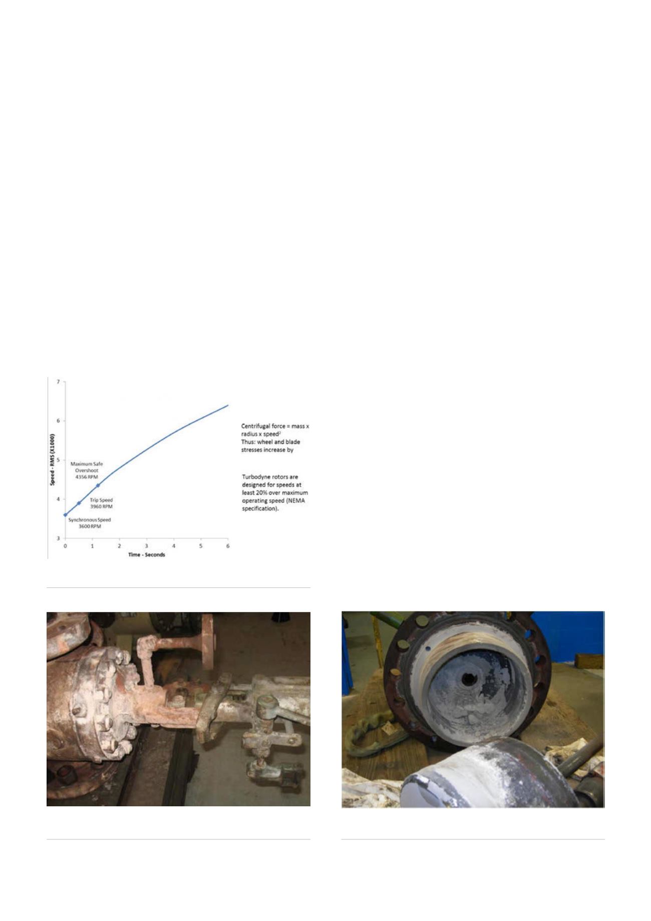
Figure 1.
Simplified acceleration curve for a typical turbine
generator.
58
World Pipelines
/
MARCH 2016


