40 |
Oilfield Technology
June
2016
wire that was required to extend through the third party tool.
Although cumbersome and to some degree limiting the tools
which could be run, it was essential for communicating with the
portion of the tool responsible for controlling the orientation the
tool moved in. Later, after further testing, a ‘wireless’ version of
the tool was produced. The wireless iteration includes a wireless
sub that allows communication to the steering section of the
tool without requiring modifications to the third-party tool. This
increased the overall flexibility of the tool and widens the range
of applications for the operator.
Tool hardware
Well hardwarescanner (WHS)
Within a well completion the metallic components such as casing
collars, perforation holes and sliding sleeves, create varying
fluctuations in any electromagnetic field which is induced
around them. The WHS monitors these magnetic variations
very precisely to determine where exactly in the completion
the toolstring is located and, more to the point, where the
entrances to lateral windows are located. The WHS does this
with a number of magnets and magnetic sensors placed in a
grid pattern. Sensors then measure the magnetic field’s angle
in relation to the tool’s axis. The tool’s geometry relative to
the surrounding casing material creates anomalies in the
magnetic field. This information provides depth measurement,
lateral window identification, lateral entry confirmation, tool
speed and direction, and distinction between openhole (OH)
and cased-hole (CH) environments. The tool also incorporates
an accelerometer for inclination data. Figure 3 shows a
representative WHS log over a CH lateral junction. The wide
spacing, very low signal strength correlates to a junction where a
lateral exits the main wellbore.
Well ultrasonicscanner (WUS)
The WUS uses transducers and range-finding principles of
time-of-flight measurement for ultrasonic signals to determine
the casing environment. Ultrasonic transducers face outward
from the outer diameter of the tool. These transmit signals
sequentially while the transducers monitor the echo return time
and amplitude response of the signals. This tool also incorporates
an accelerometer for inclination. Figure 4 shows a graphic
representation of the transducer signal emitting from the tool.
The transducers map the inside diameter of the wall opposite
of the tool, thereby identifying the surrounding wellbore
environment. Software located on the surface interprets the
signals sent and received by the WUS to determine spots of
diverging radius. This information identifies areas like washouts
or sidetracks, for example. The WUS provides lateral window
identification, lateral entry confirmation, orientation and the
distinction between OH and CH environments. Figure 5 shows a
comparison of multiple passes in the mainbore and two different
laterals mapped by the WUS.
Wireless sub
The wireless sub enables communication with the steering joint
of the multilateral intervention tool wirelessly. This eliminates
the need for 3
rd
party tools to be thru-wired, thus increasing the
flexibility of what can be run in combination with the multilateral
intervention tool. The wireless sub contains batteries for 12-hours
to activate and steer the joint from surface in response to the tool
outputs.
Electromechanical actuator–steeringaccesssub(SAS)
The SAS uses the information obtained from the sensors and
known wall-path reference points to maneuver into the various
laterals. This maneuver is completed in two steps. First, the
steering joint pivots around its central axis towards the direction
of the centre of the lateral. Next, the hydraulic piston in the SAS,
controlled from surface, can orient the joint in any direction in
15˚increments.
Fieldtrials
The multilateral intervention tool went through a number of field
trials on wells in Saudi Arabia entering many different wellbore
types; some had been completed with a CH main bore and
OH laterals while others had been completed with an OH main
bore and OH laterals. These field trials proved the tool’s sensor
ability to accurately scan the main bore at the depths required.
The sensors were able to identify the position, depth and direction
of the lateral window and guide the bottom hole assembly (BHA)
into the required lateral in the wellbore. Additionally, the field
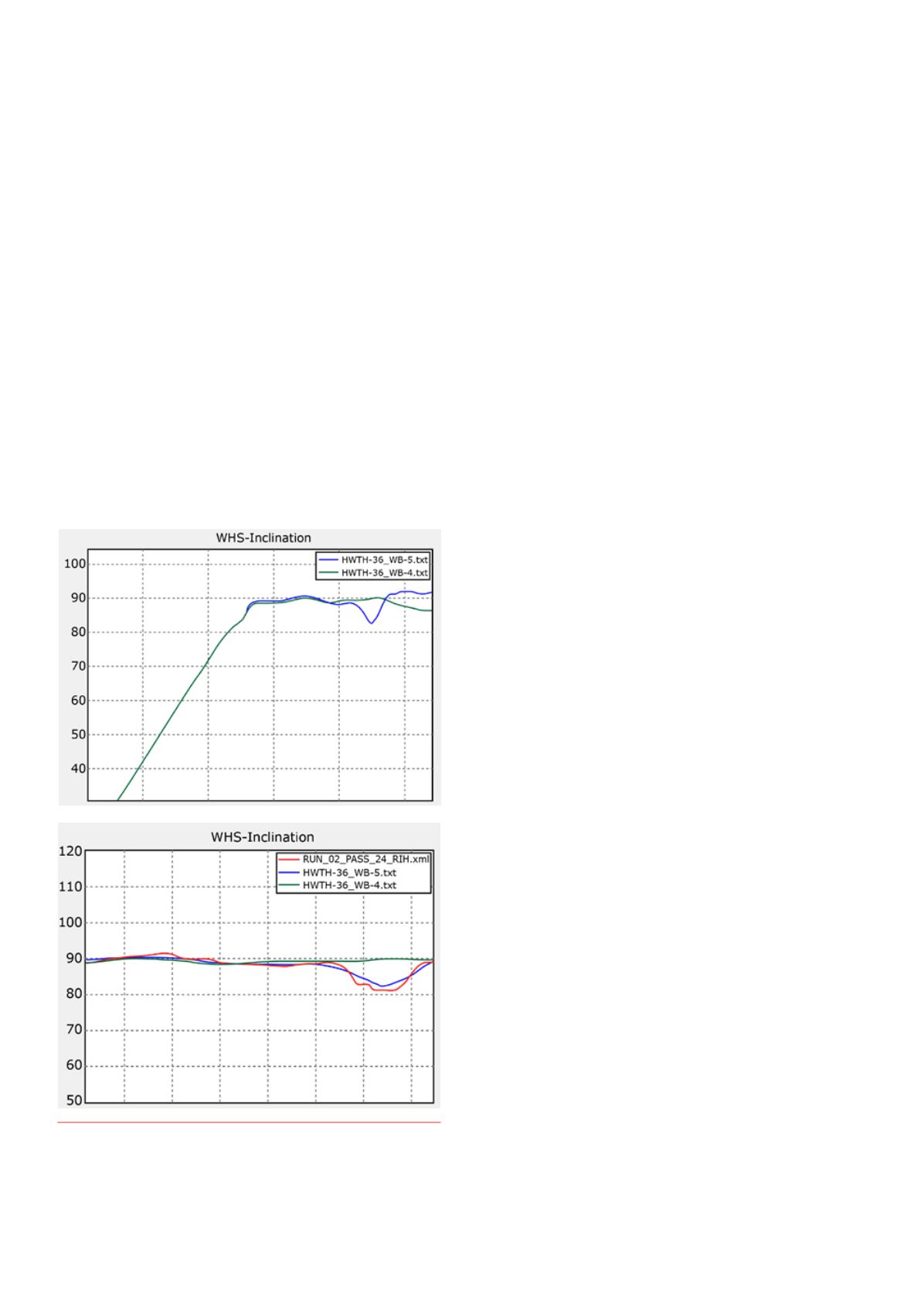
Figure 6.
Graphs showing readouts fromtheWHS for a lateral.
Inclinationanddepthwere recordedandused to locatewhich lateral the
tool was entering in thewellbore.


