56 |
Oilfield Technology
May 2016
lw d/mwd Q&A
Danny Broughton,
Enteq, UK.
Drillingdynamics
The pressure to deliver wells quickly and cheaply has never
been greater and understanding what is going on at the BHA is
critical when maximising efficiency.
Using sensors that measure shock, vibration and other
forces acting on the BHA can help understand the dynamics
the drill string is experiencing and allow the driller to rapidly
optimise operations and keep the drilling hardware within
safe tolerances, minimising failures which may necessitate
expensive trips out of the well.
The energy that goes into creating abnormal drilling
dynamics such as whirl or stick-slip is particularly hard on
the sensitive electronics of the directional package and LWD
sensors resulting in the accelerated ageing of components.
The vicious circle continues as this damaging energy is
actually leeched from the primary objective – driving the bit
forwards.
The challenges of measuring drilling dynamics in situ have
been numerous.
Firstly the shock and vibration measurement sensors have
to be appropriate for the dynamic environment they operate in.
The ultra accurate accelerometers in the directional package
are geared to measuring the earth’s gravitational
field and are no use measuring forces equivalent to
crashing a car into a concrete block at 200 mph.
The number and orientation of the shock
sensors must accurately capture the 3-dimensional
forces at play if one is to understand what is
happening and then act on it. Measuring the forces
on all three axes has been a vital step forwards in
this respect.
Location of the sensors is also critical. Most
equipment designers normally try to isolate
sensitive electronics from drilling forces using
shock mounts or floating encapsulation but for
representative measurement of real the shock and
vibration, it is necessary to be sure that the sensors
are seeing exactly what the BHA is seeing. This
necessitates hard mount coupling of the sensors to
the BHA.
Once the sensor data has been gathered, it
has to be turned into information that can be used
real time. Low data transmission rates using mud
pulse necessitates smart firmware to process raw
data downhole and generate easily transmittable
warning flags that the driller can act on.
Electromagnetic telemetry
After many years of being a marginal service,
EM technology has recently taken some large steps
forward which should see it become a much more
commonly used option or supplement to mud pulse.
Last generation EM systems faced two
challenges; issues that were not enough to
outweigh the significant advantage of much higher
speed data transmission rates, which would allow
for faster surveys and ultimately greater ROP.
EM’s biggest issue was its unpredictable
operating window. This window was a function of
depth, heavily influenced by formation resistivity
Figure 1.
Themudpulser.
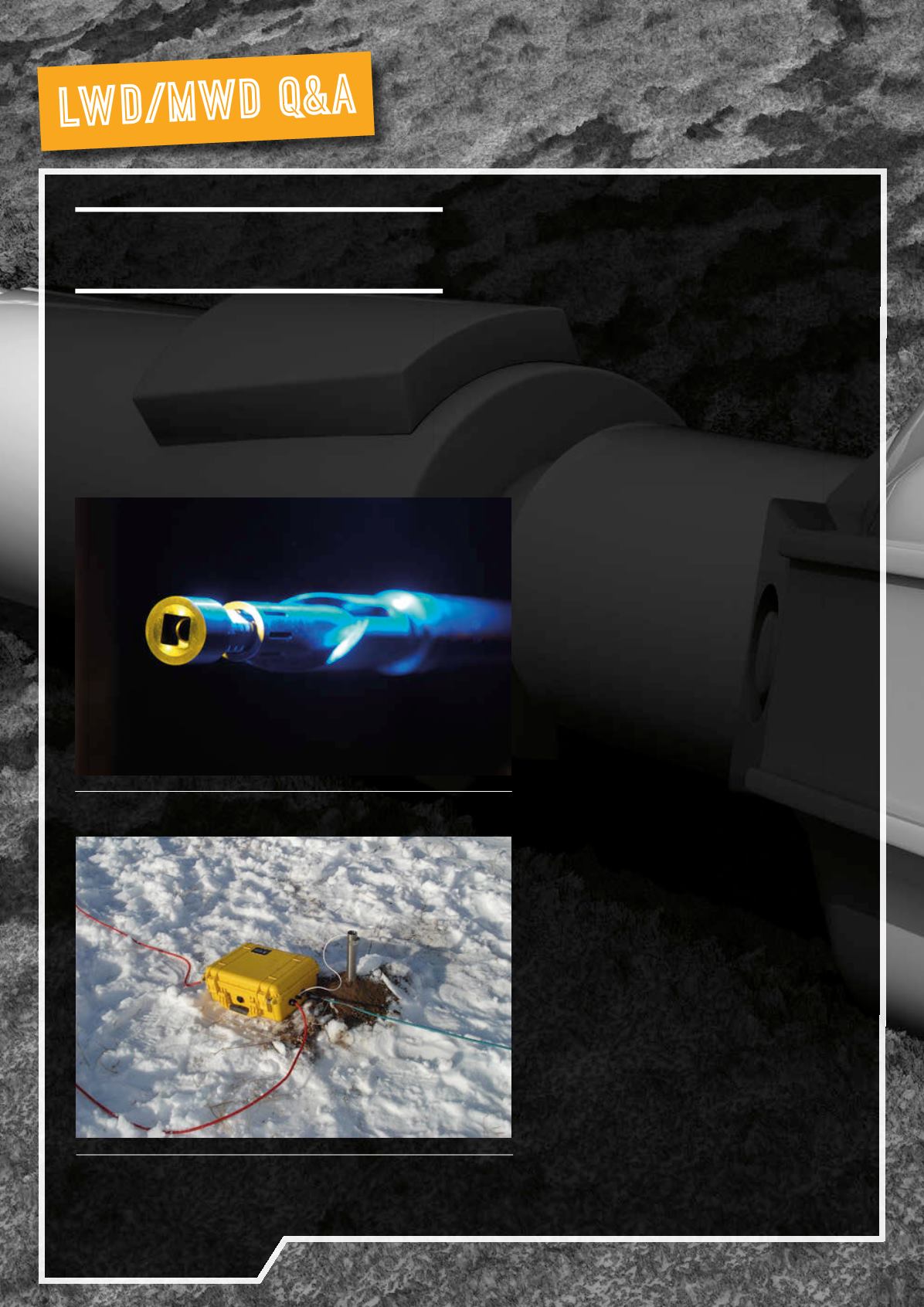
Figure 2.
Installation of EMat thewellsite.


