June
2016
HYDROCARBON
ENGINEERING
28
various flare header configurations possible to suit different
project requirements. Some of these are described below:
n
n
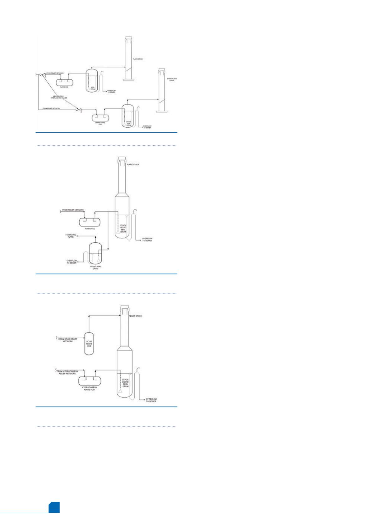
100% standby flare: a 100% spare flare knockout drum,
liquid seal drum and stack are provided, which would
ensure 100% availability of the flare at all times (Figure 1).
Mechanically interlocked isolation valves, along with well
documented safe operating procedures, are used to line up
Figure 3.
Low capacity sour flare tied in to
hydrocarbon flare stack.
Figure 1.
Mechanically interlocked, 100% spare flare.
Figure 2.
Ground flare operating in conjunction with
elevated flare.
the spare flare. The two stacks with demountable tips, one in
operation and one on standby, are mounted on a common
derrick structure so that the spare tip can be lowered for
inspection without shutting down the operating flare. The
flare regulations followed in some countries, e.g., Russia,
1
require the provision of a 100% spare flare knockout, liquid
seal drum and stack.
n
n
Separate low pressure (LP) and high pressure (HP) flare: in a
very large refinery or petrochemical complex where several
hundred pressure safety valves (PSVs) have widely different
set pressures, and high loads from the PSVs have high set
pressures, the overall system economics may favour the
provision of separate HP and LP flare headers. This is so that
higher back pressures can be permitted at the outlet of those
higher pressure PSVs, thereby reducing the diameter of the HP
flare header. The provision of separate smaller HP and LP
knockout drums, rather than a single large common knockout
drum, can also be explored. However, the flare design
regulations followed in some countries
1
require that
dedicated HP and LP flare systems should be provided and all
relief valves set at 30 bar (g), or higher, need to be connected
to the HP flare.
n
n
Two separate headers connected to a single knockout
drum: sometimes, from a layout perspective, it may be
possible to route two separate flare headers to a single
knockout drum by separate inlet nozzles, so that even if
there is simultaneous flow in both the headers during peak
flaring, only the common outlet header from the knockout
drum to the stack, which is not expected to be long, is sized
for the total flow.
n
n
Combination of elevated and ground flare: an enclosed
ground flare needs to be considered in case the plant is
located in an environmentally sensitive area (e.g., a densely
populated area or one in which there is a possibility of
disturbing the local fauna). However, the ground flare
becomes uneconomic if the peak flaring load is very high. In
such cases, the combination of an enclosed ground flare
operating with an elevated flare stack can be explored
(Figure 2). The peak flare load can be diverted to the
elevated stack by means of a properly designed liquid seal
drum.
n
n
Sour flare header of low capacity tied in to a hydrocarbon
flare: in a refinery where the peak sour flare relief load was a
small fraction of the peak hydrocarbon relief load, the heat
traced sour flare header was tied into the common elevated
stack at the base of the molecular seal (Figure 3). The
metallurgy of the stack, tip and molecular seal were selected
considering the composition of the sour gas.
Sizing of the relief network
The sizing of a relief network is critical for the safety of the entire
facility. An improperly sized relief network could lead to excessive
vibrations and the possible rupture of a flare header/sub-header,
which could cause major accidents in an operating plant. The
availability of commercial software usually equipped with inbuilt
thermodynamic models, for the sizing of relief networks, has
greatly reduced the effort required for sizing a relief network,
although the user needs to pay careful attention to the inputs
being used by the program (a relief model checklist is presented in
Table 1).
Some of the major items that need to be carefully reviewed
when sizing a relief network are:
n
n
Back pressure at unit battery limit: in a large complex with a
large number of relief valves from several process units,


